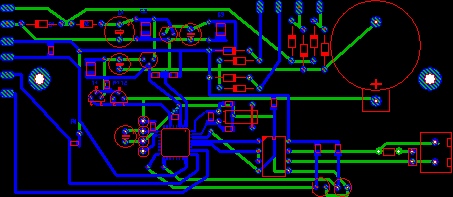
Sprint Layout offers all necessary functions to
draw the layout of a printed circuit board.
- Tracks / Lines
- Pads, Through pads (Vias), Drill holes
- SMD-Pads
- Circles / Segments
- Zones
- Polygons
- Labels
The left toolbar offers buttons that activate the
desired drawing mode for these elements. The
default mode (arrow) is the edit mode. Use the default edit mode to select, move or modify objects of the layout.
Tip:
A local popup menu opens if you press the RIGHT
mouse button on the editor. It offers
often-used functions.
Selecting objects
You have to select objects of the layout to move
or modify them. This is done in the default
edit mode (arrow). Simply click to an element to select it. Selected elements
will change their color to
magenta.
If you have to select more than one element, you
may also draw a frame (starting at an unused
position). All elements that cross the frame will be selected.
If you have to add or remove single elements
to/from the selection hold down the SHIFT key
on your keyboard and click to the element.
Moving elements
Select the elements that you want to move. Then
click to one of the selected elements and hold
the left mouse button down. Move the elements to the desired position and release the mouse button to drop them.
Hold down the CTRL key of your keyboard, to turn
off the grid-capture, if you have to reach
positions that are off the grid.
Tip:
You may also use the ARROW
keys of your keyboard to move selected elements.


No comments:
Post a Comment