Tuesday, December 30, 2014

Text

To create a text-label, press the corresponding button in the toolbar on the left:
create a text-labe
The following dialogue appears:
The following dialogue appears
Enter your text to the dialogue and adjust additional parameters like height, style, orientation, etc. Confirm your inputs with OK. You may now add the text several times to the layout with a single mouse click at the desired position.
 
Use the Automatic option to create labels with consecutive numbers (like R1,R2,...).
 
Tip:
Hold down the CTRL key on your keyboard to reach positions that are off the grid.
 
Modifying existing text-labels
To modify a text-label, just doubleclick on it. It appears the previous dialog, where you can make your changes.
Polygons

The polygon mode was designed to simplify drawing of polygons with identical angles between its segments. These polygons can be used excellent as a construction-help. For example, if you need a component with 12 pins arranged in a circle, you can create a 12-sided-polygon, place a pad on every edge and delete the polygon.
 
Select the corresponding mode with the button from the toolbar on the left, to draw a polygon.
 
polygon
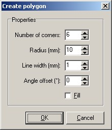
The following dialogue will appear:
 CREATE POLYGON
Enter the following parameters to the dialogue:
 
  • Number of corners (1.99)
  • Radius (measured from the centre to the corners)
  • Outline width
  • Offset (changes the start angle with a range of –180°...+180° degree)
  • If the option FILL is selected a closed area will be created. Otherwise the polygon is drawn with track segments.
 
Confirm your parameters with OK. You may now place the object several times anywhere on the board. The right mouse button returns to the default edit mode.
 
Tip:
Hold down the CTRL key of your keyboard to reach positions that are off the grid.
 
Modifying existing polygons
Filled polygons may be changed as any other zone or track.

Zones

Zones are filled areas (polygons). Zones, that are drawn on the copper layer and connected to certain signals, are also called planes (ground plane, power plane, etc.). The outline of zones is drawn in the same way as tracks, where the outline width determines the radius of the zone corners. Sprint Layout closes and fills the polygons automatically.
 
Select the corresponding mode with the button of the toolbar on the left, to draw a zone:
draw a zone
 Move the mouse cursor to the layout. The cursor will appear with the diameter of the track width. The first click defines the start point of the zone outline. Now move the mouse to the destination point of the outline segment. Use the SPACE key of your keyboard to find the optimal route for the segment. Click again to fix the segment and continue with the next segment. Use the right mouse button to finish the process. The polygon is then closed and filled automatically. You need at least three points for a zone. Otherwise no zone will be created. A zone is also finished if you close it manually.

Circles

To draw a circle set the corresponding mode with the button of the left toolbar:To draw a circle set the corresponding mode
 
Move the mouse cursor to the layout. The cursor will appear with the diameter of the track width. This is also the width of the circle. Click on the desired centre position of the circle and define the diameter moving the mouse. Then you release the mouse button, and the circle will be created. Use the right mouse button to abort the process.

SMD-Pads

To place SMD-pads select the corresponding mode with the button from the left toolbar:
To place SMD-pads select the corresponding mode
Move the mouse cursor to the board while the SMD-pad mode is selected. Every click will add a pad to the layout. The SMD-pad mode may be aborted by pressing the right mouse button.

Pads, Vias, Drill holes

To place pads select the corresponding mode with the button from the left toolbar: 
pads select the corresponding mode
Sprint Layout offers several shapes for pads. The current shape is displayed on the button. To select another shape, click to the arrow button right from pad button.
 If the option THROUGH PAD is selected the pad will appear on both sides of the board automatically. This is indicated by a hatched display and a red colored hole.
 Move the mouse cursor to the board while pad mode is selected. Every click will add a pad to the layout. The pad mode may be aborted by pressing the right mouse button.

Tracks

Tracks
 
To draw a copper track select the corresponding mode from the left toolbar:
 
left toolbar
 
Move the mouse cursor to the layout. The cursor will appear with the diameter of the track width. The first click defines the start point of the track. Now move the mouse to the destination point of the track. Use the SPACE key of your keyboard to find the optimal route for the track. Click again to fix the track and continue with the next segment. Use the right mouse button to abort the process.

Basic drawing functions

Sprint Layout offers all necessary functions to draw the layout of a printed circuit board.

Saturday, December 27, 2014

Ruler and coodinate display

Rulers
Sprint Layout offers rulers on top and on the left of the editor. The scale units may be switched between inch (I) and millimetre (M) with the push button between the rulers. (Also available from the OPTIONS item of the main menu.) The current mouse position is marked for better orientation.


Solder layer and silk screen layer

Sprint Layout offers four layers. Imagine layers as transparent films that lay on top of each other. There are two layers for each side of the board, one for the copper layout and one so-called silk screen layer that is used for the component print of the board.
 

Grid size

The grid allows you to place layout elements precisely and very efficiently. The grid capture is always active and is displayed as long as the zoom is adjusted to appropriate values. The grid display is disabled when zoom factor is too small to display the grid, but the capture will still remain active.