Showing posts with label program Sprint Layot. Show all posts

Monday, January 5, 2015

About programm Sprint Layot

Sprint-Layout 4.0
Sprint Layot v.4
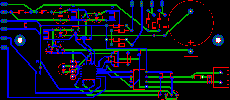
Sprint-Layout is a simple tool to create layouts for single-sided and double-sided PCBs (Printed Circuit Boards). The software comes along with all functions that are necessary for board design. Even professional features, like export of Gerber-files, are included, while the handling of Sprint-Layout was kept self-explaining.
Sprint-Layout is equipped with tools to draw solder pads, SMD pads, tracks, zones, text-labels and so on. You can select from several types of solder pads, which are sizeable in wide range.
There are two layers – copper and silk screen - for each side of the board. Additional features are solder masks, ground planes, signal flow test etc.
The integrated autorouter may help you to route tracks.
 The photoview option allows you to take a look at your board, as if it was manufactured. This may help you to find faults on your board.
 The extendable library is predefined with several components, even for SMD layouts.
 Lots of options are selectable, when printing the layout, the component mounting plan, or the solder mask on paper or film.
 You can even create Gerber- and Excellon-files, to send track and drill information to professional board manufacturers.

New features of Sprint Layout 4.0

Autorouter
Sprint-Layout is now including an easy to use point-to-point autorouter. The autorouter transforms your connections into tracks automatically. Routed tracks can be resolved again with one click. So you can easily control the sequence and the result.
Free layer
You can now edit all layers simultaneously. In the previous versions there were some troubles because of the layer-separation, especially when using SMD and "normal" components together. Now you can edit single- and doublesided boards as easy as never before.

Sunday, January 4, 2015

Using the clipboard

The well-known functions of the EDIT item of the main menu refer to the clipboard and may be performed on selected objects:
 
  • Cut
  • Copy
  • Paste
  • Duplicate
 
These functions are also available from to toolbar on top of the editor.

Zoom

To adjust the zoom click to the corresponding button in the toolbar on the left:

Zoom
The mouse cursor changes to a magnification glass. A click with the left mouse button increases the zoom. The right mouse button decreases the zoom. You may also draw a frame to select the detail to be zoomed.

Rotating, mirroring and adjusting objects

These functions are available from the FUNCTIONS menu or from the toolbar. You may also call these functions from the local popup menu of the editor (right mouse button).
 
rotate
Rotate
This function rotates all selected elements with a step of 90 degrees clockwise.
 mirror horisont Mirror vertical / horizontal
All selected elements are mirrored horizontal or vertical.
 Adjust Adjust
This function adjusts all selected elements. You can select between top, bottom, left, right, horizontal-centre or vertical-centre alignment.
 Adjust to gridAdjust to grid
This function forces all selected objects to grid positions. Caution: This may change the distance of objects that are not grouped. The relative positions of objects that are combined to groups will not be affected. In case of groups the whole group is moved.

Working with grouped elements

Elements of a layout can be combined to groups. Groups make it easier to select, move or edit all members of a group with a single operation. Groups also protect their elements against unwanted changes. You can not delete elements that belong to a group. At least two elements are necessary to create a group. Groups can contain any elements of a layout, even other (sub-) groups.
 
If you have to delete or modify individual elements of a group, you must first split the group. Only the top-level group is affected when a group is split. Subgroups stay unaffected, but you may repeat the split operation to split a subgroup.
 
BUILD GROUP ungroup
Call BUILD GROUP or SPLIT GROUP from the FUNCTIONS item of the main menu or from the toolbar. These functions are also available from the popup menu (right mouse button) of the editor.
 
Sprint Layout will group elements automatically when they are pasted from the clipboard or from the component library. This makes it easier to place the elements. You can split these groups as any other groups.

Connections (Rubberbands)

With the connections you can connect pads or SMD-pads of your layout. This is helpful not to forget to route tracks.
 
The connections are also very important for the work with the integrated autoruter. The autorouter uses these connections to route tracks.
 
The connections, displayed as thin rubberband-lines, are also helpful to find a suitable position for components. You may use them to avoid crossing tracks when placing components on the board.
 
To place connections on your board, activate the connection-mode with the corresponding button from the toolbar on the left:
connections
 
Connections can only be drawn between pads or SMD-Pads. Just click on the first pad, you want to connect. After that, a rubberband "sticks" on your mouse cursor. Now click on any other pad to finish the connection. Pads will light up when they are touched to make connecting easier.
 
Click with the right mouse button, to abort the process.

The Autorouter

A simple point-to-point autorouter is integrated in Sprint-Layout. This autorouter is able to connect two points of your layout. These two points are defined with a connection (rubberband). The autorouter was not designed, to generate whole boards at once. This is usually not possible. To create a proper layout, you have to design it mostly by yourself.
 
The autorouter in Sprint-Layout is designed as an easy-to-use autorouter. You don't have to set obscure specifications and options. The autorouter is as simple as the whole software itself.
 
To use the autorouter, select the corresponding button in the left toolbar:

autoruler
A small tool-window appears with the available options for the autorouter:
autoruler

Testing a board

Sprint-Layout finds connected tracks, pads and other areas of a board. This makes it easy to check the signal flow of the layout. Connected areas will light up.
 
Activate the test mode with the corresponding button of the toolbar on the left:
The mouse cursor will now appear as a "signal injector”. Simply click to any position of your layout and Sprint-Layout will find all tracks, pads and other areas that are connected to the click position. Connections via trough pads, and tracks from both sides of the boards are also considered in test mode. You may now click to another position or cancel the test mode with the right mouse button. 

Measure

With this function you can easily measure distances and angles on your layout.
To select the measure-mode, just click on the button in the toolbar on the left:
 
Measure
You can now click on any position on your layout and draw a frame:
 
position on your layout and draw a frame
You will see the the following values:
 
  • dX: Distance in X-direction (horizontal distance)
  • dY: Distance in Y-direction (vertical distance)
  • Distance: Absolute distance between the edges (diagonal)
  • Angle: The angle of the diagonale
 
With these values, you can measure your layout exactly. Measurements will become more accurate, when details are zoomed.
 
With a click on the right mousebutton you can exit the measure-mode.

The Ground-Plane function

This function fills unused areas of a layout with copper automatically. This accelerates the corroding process and saves corroding material. You may also use this function to create a screen for HF-boards. Please consider that the function creates an area that is NOT connected to any signal of the board. So you may have to connect the area to GND yourself, if necessary.
 
The function "Ground-Plane” is available for both sides of a board. To activate/deactivate the ground plane, click to the corresponding button on the bottom of the editor:

Ground-Plane
The function Ground-Plane is now activated and will be displayed in your layout.
You may turn on/off the ground plane whenever you like, without any loss of information.
 
You may adjust the distance between ground plane and existing tracks, pads and other elements. The distance is adjustable for each individual element of the layout with the input field on the right of the ground plane button (only visible if ground plane is activated). Therefore select some elements first.
 
Simply enter a new distance value and all selected elements change their distance from the ground plane. New elements use the current distance value.
 
A distance of 0 contacts the selected elements to the ground plane!


Photoview

The photoview lets you take a look at your board as if it was already manufactured, with drillings, silk screen, etc. This helps you to find typical mistakes like wrong mirrored components or text.
 
To activate the photoview, just click on the corresponding button in the left toolbar:
 
photoview

Keyboard control

The keyboard offers some additional functions and makes functions more convenient to use:
 
CTRL-key
Hold down the CTRL-key to turn of grid capture temporary, whenever you have to reach positions that are off the grid.
 
ARROW-keys
Use the ARROW-keys to move selected object in steps of one grid position. The combination with the CTRL-key allows steps of 1/100 mm.
 

Editing more than one board

When you are working on a project that consists of several boards, you can save all boards to one single project file on disk. The board selector on bottom of the editor offers an entry for each board of the project:

board
A click to one of the entries shows the corresponding layout in the editor. A click with the RIGHT mouse button opens a local popup menu that offers additional features of the board selector. These functions are also available from the BOARD item of the main menu.

AutoSave

The AutoSave option saves your work regularly. You may activate this option and select the save-interval. Call AUSOSAVE from the FILE item of the main menu.

autosave
If the AutoSave option is activated, Sprint-Layout creates a backup file (*.bak) of your project and saves all changes to this file in regularly intervals. The project file (*.LAY) remains unaffected, so do not forget to save your work even if AutoSave is activated.
 
If you lost your project (*.LAY) for any reasons, you may change the extension of the backup file *.BAK to *.LAY to recover your work.

Scanning and copying layouts

Scanned layouts from magazines may be used as copy for reproduction or for simple extensions. The layout must be available as a bitmap file. The bitmap is displayed in the background of the editor.
 
Make sure that the bitmap file is monochrome (black & white). If the scanned file has a different file format, use a graphic application to create a suitable file.
 
A bitmap resolution of 600 dpi is to be recommended. Lower resolutions will cause loss of quality. Higher resolution will waste memory without gain of quality.

Macros

The component library of Sprint-Layout consists of so-called macros. Macros are small layouts of recurrent elements (mainly components like resistors, transistors, etc.).
 
Sprint Layout is delivered with several pre-defined macros. You may use these elements for your layout or create your own macros as well. See also...

Using macros

To use the macros in your layout, you have to open the macro-library first. Select MACRO LIBRARY from the OPTIONS menu, or click on the corresponding button in the toolbar:

macros

The macro-library will apear on the right.

Thursday, January 1, 2015

Creating user-defined macros

There is no difference between drawing a macro and drawing any other layout. Use the copper layer (C1,C2) for pads and tracks and the silk screen layer (S1, S2) for component outlines. Outlines are simply drawn with ordinary layout elements (circles, tracks, etc.) on the silk screen layer.
 
Please take care that your component is lying on the board-side 1, when creating a macro.
 
This means layers should be used as follows for macros: The silk-screen-layer should always be S1 (component is lying on board-side 1). Then the copper-layer should be C1 for SMD-components or C2 for "normal" components.
 
Example:
Let´s say you want to create a simple macro for a DIL 14-pin-IC.

(This is only an example. Of course, a 14-pin DIL-IC is already included in the macro-library.)

1. Draw the Macro
Place the 14 pads on the layer C2 (copper-bottom) in the right grid distance. You may create a square-pad for the pin1, to identify this pas as "Pin 1".
The component outline should be lying on the board-side 1 (S1). This means that the pads, which are on the other board-side, must be placed on layer C2.
Select C2 as the active layer and add 14 pads in the correct arangement.
Change the active layer to S1 and draw a rectangle around the pads, using the normal track-function.
Mark the "nose" or the pin 1 of the IC to define the orientation.
Just use a track or the rectangle-mode to draw this frame. You may draw an additional mark to identify the notch of the IC.
That's it, your macro is ready. You will now have to save it and add it to the macro-library.
 2. Select the macro-elements
 Change to the edit-mode and select the elements by drawing a frame around all elements.
Change to the edit-mode and select the elements by drawing a frame around all elements.
All elements are now selected.

3. Save the Macro

The function SAVE AS MACRO from the FILE menu saves the current layout (or the current selection) to a macro file to disk. You can also click the correspondig button in the macro-library. The following dialog allows you to enter a filename for the macro, and to select the directory, where the macro will be saved. The default extension *.LMK (which is the default suffix for all macros) for macros is added automatically.
 
You may save the whole layout or parts of it as a macro. If parts of the current layout are selected, only the selected parts are saved to the macro file. If nothing is selected the whole layout is saved as a macro (after confirmation). 


It's completely free. If you need to transfer, send or receive money or find Western Union locations, you can use a very convenient website locnearby.com

Deleting macros

Select a macro from the library and press the DELETE button in the macro-library. After your confirmation the selected macro is deleted.
 
You may use the Windows-Explorer as well to delete or sort macros (*.LMK).