Thursday, January 1, 2015

Project info

Use this option to add copyright informations and comments to your project.
You can open the project info with the corresponding button in the toolbar:
 

info
 

project info
Now you can enter your project informations. In the comment-field, you can add annotations to your project like pin-lists, background-information, clients, etc.
The project info will be saved together with your project automatically.

Define colors

You can define your own colors for each layer, background, grid, etc.
To define these colors select DEFINE COLORS from the OPTIONS menu.

define colors
You can select one out of four colour schemes from the listbox:
 
  • Default
  • User 1
  • User 2
  • User 3
 
The colour scheme DEFAULT is the predefined colour scheme and can not be modified. You can select this colour scheme to restore the original colors.
 
The colour schemes USER 1..3 are user-definable. You can define them on your own taste.
Simply click on corresponding colour box and select a new colour. 

Directories

You can define fixed default-directories for several file types. To define the default-directories select the option DIRECTORIES from the FILE menu.
 
directories
A dialogue allows you to enter your default-directories.
 
Whenever you start the software, these directories will be used as the default-directories for saving and opening files.
 
With the "..." buttons, you can select a  existing directory from your filesystem.

Tuesday, December 30, 2014

Text

To create a text-label, press the corresponding button in the toolbar on the left:
create a text-labe
The following dialogue appears:
The following dialogue appears
Enter your text to the dialogue and adjust additional parameters like height, style, orientation, etc. Confirm your inputs with OK. You may now add the text several times to the layout with a single mouse click at the desired position.
 
Use the Automatic option to create labels with consecutive numbers (like R1,R2,...).
 
Tip:
Hold down the CTRL key on your keyboard to reach positions that are off the grid.
 
Modifying existing text-labels
To modify a text-label, just doubleclick on it. It appears the previous dialog, where you can make your changes.

Polygons

The polygon mode was designed to simplify drawing of polygons with identical angles between its segments. These polygons can be used excellent as a construction-help. For example, if you need a component with 12 pins arranged in a circle, you can create a 12-sided-polygon, place a pad on every edge and delete the polygon.
 
Select the corresponding mode with the button from the toolbar on the left, to draw a polygon.
 
polygon
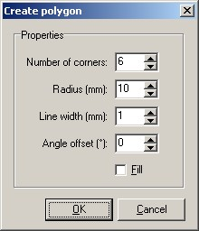
The following dialogue will appear:
 CREATE POLYGON
Enter the following parameters to the dialogue:
 
  • Number of corners (1.99)
  • Radius (measured from the centre to the corners)
  • Outline width
  • Offset (changes the start angle with a range of –180°...+180° degree)
  • If the option FILL is selected a closed area will be created. Otherwise the polygon is drawn with track segments.
 
Confirm your parameters with OK. You may now place the object several times anywhere on the board. The right mouse button returns to the default edit mode.
 
Tip:
Hold down the CTRL key of your keyboard to reach positions that are off the grid.
 
Modifying existing polygons
Filled polygons may be changed as any other zone or track.

Zones

Zones are filled areas (polygons). Zones, that are drawn on the copper layer and connected to certain signals, are also called planes (ground plane, power plane, etc.). The outline of zones is drawn in the same way as tracks, where the outline width determines the radius of the zone corners. Sprint Layout closes and fills the polygons automatically.
 
Select the corresponding mode with the button of the toolbar on the left, to draw a zone:
draw a zone
 Move the mouse cursor to the layout. The cursor will appear with the diameter of the track width. The first click defines the start point of the zone outline. Now move the mouse to the destination point of the outline segment. Use the SPACE key of your keyboard to find the optimal route for the segment. Click again to fix the segment and continue with the next segment. Use the right mouse button to finish the process. The polygon is then closed and filled automatically. You need at least three points for a zone. Otherwise no zone will be created. A zone is also finished if you close it manually.
Circles

To draw a circle set the corresponding mode with the button of the left toolbar:To draw a circle set the corresponding mode
 
Move the mouse cursor to the layout. The cursor will appear with the diameter of the track width. This is also the width of the circle. Click on the desired centre position of the circle and define the diameter moving the mouse. Then you release the mouse button, and the circle will be created. Use the right mouse button to abort the process.